![]()
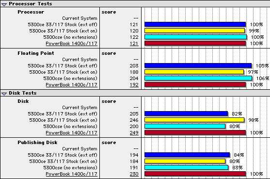
5300 OverclockI've managed to overclock a 5300cs to 5300ce speeds! That is, I changed the bus multiplier to achieve a 117MHz CPU speed from a standard 100MHz 5300cs. As far as I know, this is the ONLY website that documents this sort of modification to the PowerBook 5300 series. One thing I won't mention on this page is where to get tools or parts. For the record, I don't recommend any modifications you might perform to your hardware. I take no responsibility for any damange you do to yourself or your hardware. And, frankly, if you don't know where to get parts, or what parts to use, then you shouldn't be doing this mod anyway. The learning curve can be pretty steep too, so PLEASE, if this is your first mod and you are doing it to your only PowerBook, RETHINK IT! There are 2 ways to achieve a speed up of your stock 5300 Series machine. The first is probably the route you should go if you have little experience with board-level, surface mount soldering. Not that the components are much bigger, but there is a little more room for your soldering iron when dealing w/ the 33.3333MHz oscillator.1) The easiest way by far to speed up the 5300 series is to replace the 33.3333MHz oscillator on the mobo with a faster part. To figure out the speed of your new CPU, multiply the frequency of the new part by 3 (ie 36MHz * 3 = 108MHz - if you install a 36MHz oscillator, you'll get a 108MHz CPU). If you have a 5300ce, multiply by 3.5 (36MHz * 3.5 = 126MHz). We quickly reach a limit - chips can only run so far over their rated clock speed (even under the best of circumstances, it's hardly likely anything more than a 20 - 25% boost will be stable). So the next problem is to figure out how to change that multiplication factor from 3 (or 3.5 in the case of a 'CE) to, well, anything else (a lower multiplier will allow us a faster bus while keeping the CPU in a reasonable range).... 2) Doing this encompasses the second method for overclocking a PowerBook 5300 Series machine. The multiplier on PowerBook 5300, like many other Macs (see Marc Schrier's wonderful clock chipping website), is set by a series of resistors on the motherboard. These resistors are not documented by Apple, and it often takes some doing to figure it out. To my knowledge, no one has yet posted information about changing the multiplier on a 5300... So here goes! This is some preliminary info I have. Having a CS and CE mobo side by side, I've noticed these differences. Following a hunch, I took a look at these resistors...
I downloaded
some technical info on the PPC 603e from Motorola's website.
Page 14 of that document shows a diagram w/ the pinout of the
603e. It goes something like this:
Thanks to Dave Ip, I have a handful of 5300c mobo pics for the appropriate area. Click on the thumbnails below to view an image compressed for use on the web. Click on download original to view the image in it's full, unadulterated 1024x768 glory. P.S.: (My lawyer made me say this) These modifications are not recommended. I can take no responsibility for any bone-headed stunts you try to pull with your own hardware! ;-) Modifying your Mac in this way will absolutely void any warranty you might have left on that ancient machine. And don't try doing this if you aren't comfy with the guts of your PowerBook and don't know your way around a soldering iron... ...er, not that I really do...
|
|||||||||||||||||||||||||||||||||||||||||||||||||||
